
VAMTECH- Voltage Ampere Measurement Technology.

Logo
NUCLEAR QUALIFIED

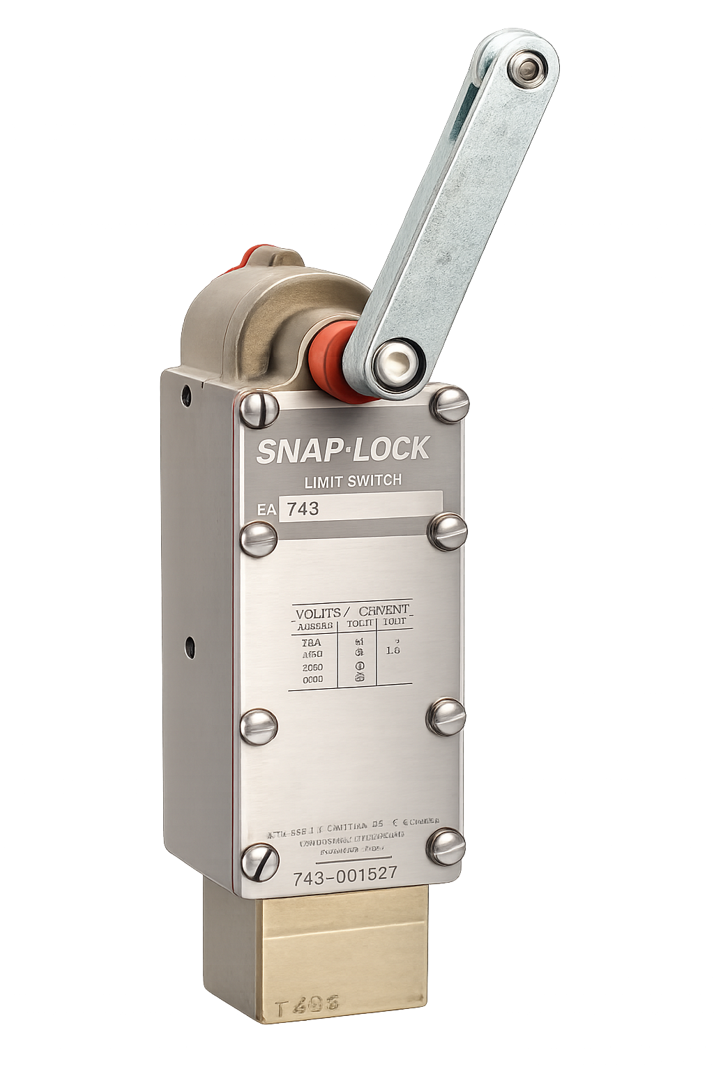
EA740 Series Harsh Environment With Accident Conditions

Double pole double throw limit switches with cam type SNAP-LOCK technology, corrosion-resistant construction, and nuclear qualified connection options.

Ordering Information

Built for nuclear qualified service

The EA740 series combines dependable contact geometry, SNAP-LOCK cam action, and corrosion-resistant materials for harsh environments with accident conditions.
Double Pole Double Throw (DPDT)
Cam Type SNAP-LOCK Technology
Qualified to IEEE Standards 344-1975, 323-1974 and 382-1972
Manufactured to a quality assurance program for 10CFR50, Appendix B and ANSI N45.2
Diecast bronze housing for corrosion resistance
Stainless steel top cover and fasteners
EA740

Precision, Packed Into
Every Switch

Contact arrangementTwo normally open and two normally closed, NEMA form Z
EnclosureMeets NEMA 1, 4 and 13 requirements
Operating leverAdjustable in 7°30' increments through 360°
Wiring spaceAdequate wiring space for nine conductors
Operating temperature21° to 90°C; short term exposure to 175°C
Pre-travel18°
EA740 Specs
Maximum travel90°
Weight4.3 lbs.; 5.3 lbs with receptacle
DBE temperature340°F
DBE pressure70 PSIG
DBE radiation204 megarads gamma

Travel Data,
One Section at a Time

Travel values and torque values are shown as separate blocks so each operating condition reads like its own PDF section.

Lever condition

Standard Contacts

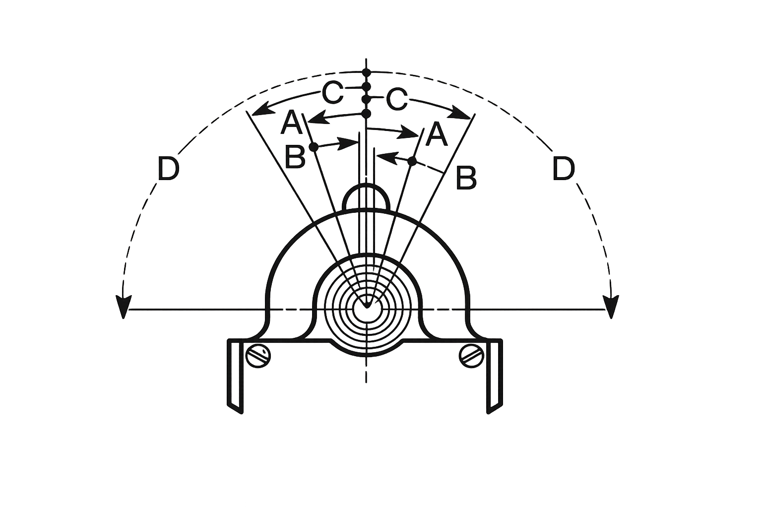
A. Trip Travel
18°
B. Reset Travel
14°
C. Recommended Travel
30°
D. Total Travel
90°
E. Torque to Trip
27
Lever condition

Maintained Contacts & Lever Position

A. Trip Travel
25°
55°
B. Reset Travel
25°
22°
C. Min. Travel to Maintain
54°
55°
D. Recommended Travel
60°
60°
E. Total Travel
124°
116°
F. Overall Travel
56°
64°
G. Torque to Trip
12
6
Lever condition

Maintained Contacts - Lever Returned

A. Trip Travel
16°
30°
B. Reset Travel
30°
26°
C. Min. Travel to Maintain
26°
30°
D. Recommended Travel
45°
45°
E. Total Travel
90°
90°
F. Torque to Trip
16.5
15
To change switch orientation from cam position left view to cam position right view, separate switch then angle and reset at initial position.
Ordering Information

Build the part number
from the PDF

The groups below reflect the PDF ordering structure for mounting, rotation direction, and nuclear qualified connection options.

Group
A: Mounting
2 - Standard Mount
5 - Wide Mount
8 - Long Mount
Group
BC: Rotation Direction
00 - Clockwise or Counterclockwise
01 - Clockwise and Counterclockwise
60 - Maintained Contact & Lever Position
67 - Maintained Contact, Lever Returned
Group
DE: Nuclear Qualified Connection Option
00 - Open Conduit Entrance Clockwise or Maintained
01 - Open Conduit Entrance for Counterclockwise
40 - 9-Pin QDC Clockwise or Maintained
41 - 9-Pin QDC for Counterclockwise
50 - 4-Pin QDC 1NO/1NC Clockwise or Maintained
51 - 4-Pin QDC 1NO/1NC Counterclockwise
52 - 4-Pin QDC 2NO Clockwise or Maintained
53 - 4-Pin QDC 2NO Counterclockwise
54 - 4-Pin QDC 2NC Clockwise or Maintained
55 - 4-Pin QDC 2NC for Counterclockwise
Outline Drawings

Standard, wide, long and quick disconnect mounting

Click a section heading to show the matching drawing image and the travel notes shown in the PDF.

The outline drawing sheet in the PDF is used to verify installation space, lever travel direction, mounting style, and terminal layout before selecting a part number.

What the drawing shows

The diagrams identify the mounting footprint, pipe tap area, quick disconnect locations, and the A through G travel callouts used in the PDF tables.

How to read it

Start with the mounting style, then confirm the travel table, then check the pipe tap and hole pattern against the enclosure layout.
Reference panel
Standard Mounting
Standard Contacts
Related drawing and travel notes
1
Standard Mounting

Shows the standard switch mounting style, the pipe tap reference and the A to E travel notes.

A. Trip TravelB. Reset TravelC. Recommended TravelD. Total TravelE. Torque to Trip
PDF section detail
Standard: Standard Contacts
Wide: Maintained Contacts & Lever Position
Long: Maintained Contacts - Lever Returned
QDC: Quick Disconnect Mounting

Need Technical Assistance?

Contact our engineering team for datasheets and integration support.