
EA780/790 SERIES Navy-Marine Position
PH 800.390.6405 | customer.service@sptech.com | www.namcocontrols.com
Built for Navy/Marine Requirements
1NO/1NC, 2NO/2NC, 2NO, 2NC, 4NO, 4NC
Cam-Type SNAP-LOCK® Technology
Three Mounting Styles Available (Standard, Wide, Long)
Built for Navy/Marine Requirements
Completely fabricated from non-corrosive materials, including a bronze enclosure and stainless steel shaft
Heavy Duty Electrical Contacts EA780 - Sliding Type; EA790 - Butt Type
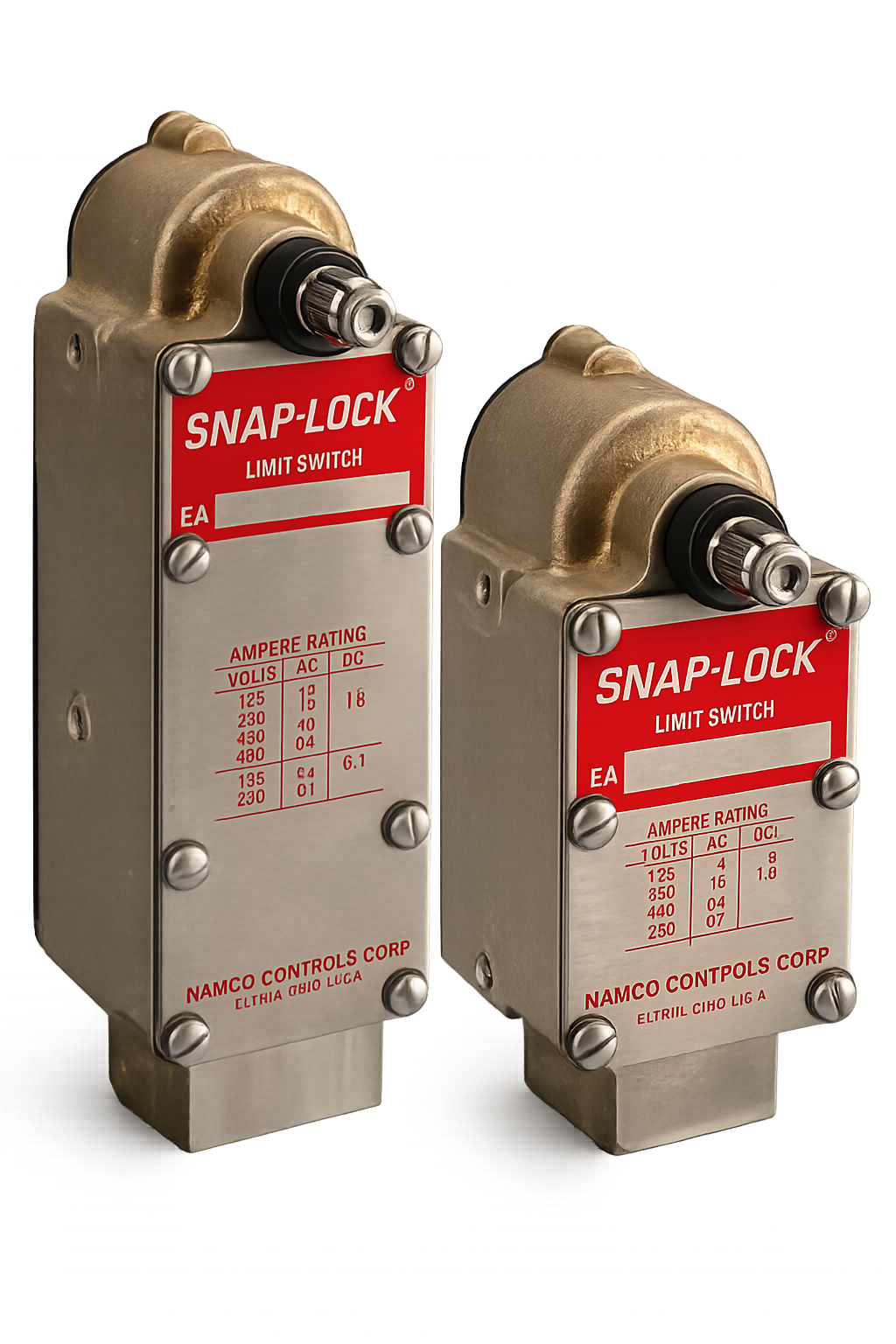
Technical Data
and Ratings
Typical Cams
The versatility of the Snap-Lock mechanism is achieved with the use of a series of uniquely designed cams.
Built into the standard switch for B1 single action CW, B1 single action CCW and B2 double action CW & CCW sequences.
Designed for applications requiring a neutral position. Both lever and cam are spring returned to starting position.
Available for maintained contacts with one-direction or either-direction operation depending on the cam selected.
Operational Data
EA780/790 Series
EA780 Series & EA790 Series - B1 CAM, B2 CAM
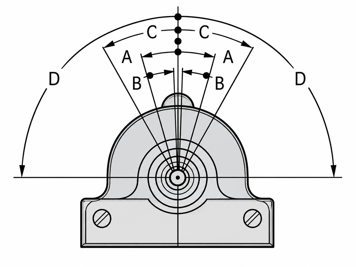
EA780 Series & EA790 Series - B1 CAM, B2 CAM
.png)
EA790 Series - B9 CAM (Short Travel)
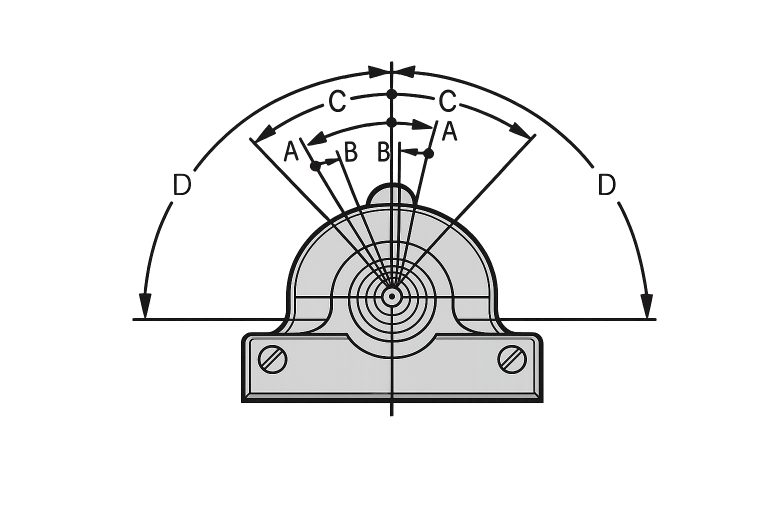
EA790 Series - N1 CAM
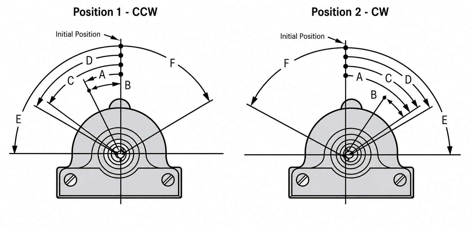
EA780 & EA790 Series - M CAM and M7 CAM
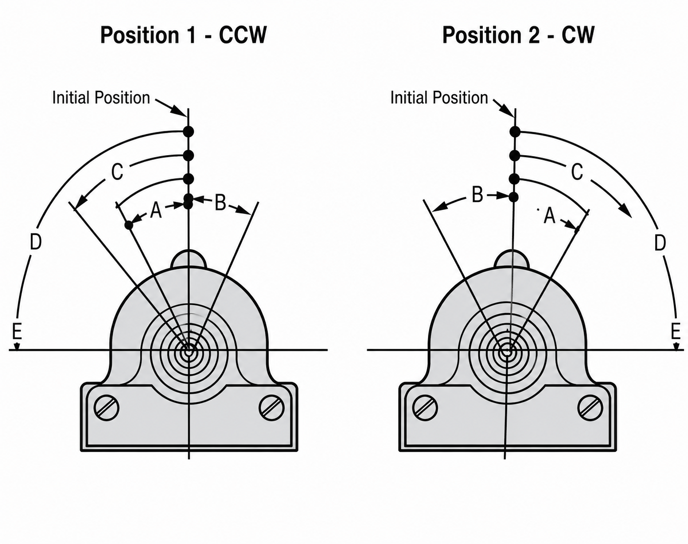
EA780 & EA790 Series - M7 CAM
Operation tables and circuit arrangements
Operation direction, initial position and circuit labels are preserved as a separate reference block.
Shown for 1NO/1NC and 2NO/2NC circuits with both clockwise and counterclockwise operation tables.
Shown for configurations that switch only in counterclockwise operation and return to initial position.
Shown for configurations that switch only in clockwise operation and use the same contact labels.
All dimensions given in Inches.
Standard Wide Long
All dimensions are shown in inches. The drawing sheet covers the standard, wide, and long mounting styles and then identifies the EA780 sliding type and EA790 butt type contact families.
The dimensions include the standard mount body, 48 serrations, pipe tap area, the .495 / .490 O.D. note and the wider long-mount envelope.
Start with the mounting style, then confirm the contact type, then verify the width, height and pipe tap values against the enclosure cutout.
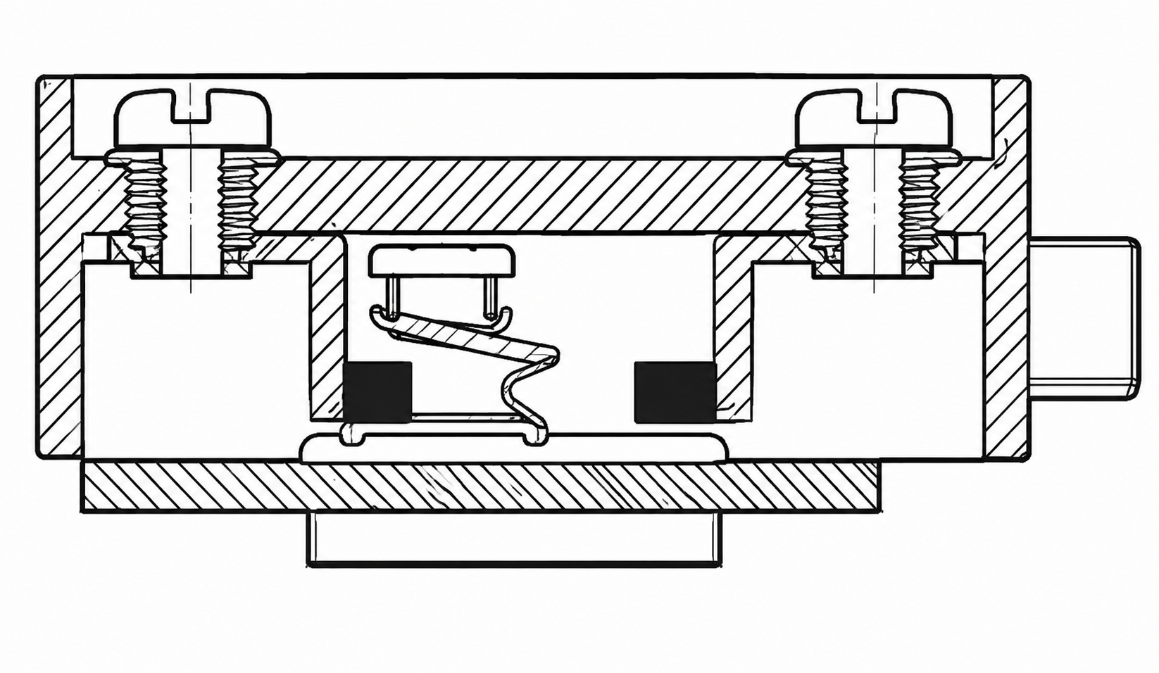
Standard mounting view showing the body envelope, pipe tap location, 48 serrations, and the outline dimensions used on the PDF sheet.
Build the part number
For additional EA780 Series options, consult factory. For additional EA790 Series options, consult factory.